


 311 / 528

Enclosed Motor Controls
Enclosed Motor
Controls
A-307
Can’t find what you are looking for? Call
1-800-ASK-4WEG
(275-4934)
Data subject to change without notice.
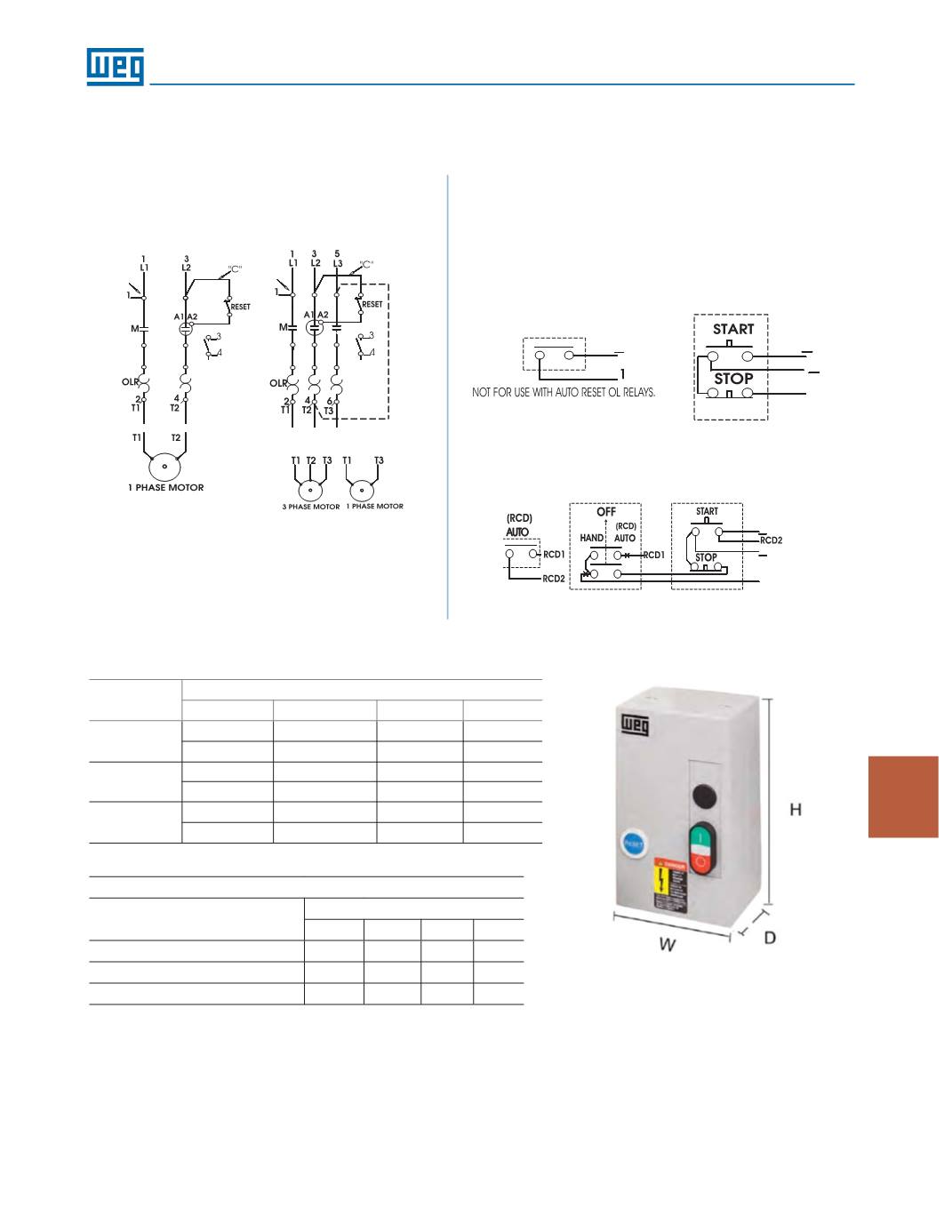
Enclosed Starters
Dimensions (approx. inches)
Enclosed Starters
Enclosure Size
BOX
H
W D
ESW(S) 9, 12, 18, 25, 32
M04
9.5
5.5
5.0
ESW(S) 40, 50, 65, 80
M06
13.0
7.5
5.6
ESW 95, 105
M08
17.8
9.5
6.7
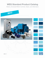
WIRING DIAGRAM
DIMENSIONS
Provision for
cable gland fitting
Standard
Top
Bottom
Side
Back
Box M04
2x (½” or ¾”)
2x (½” or ¾”)
4x (½” or ¾”)
2x (½” or ¾”)
1x (¾” or 1”)
1x (¾” or 1”)
-
-
Box M06
1x (½” or ¾”)
1x (½” or ¾”)
3x (½” or ¾”)
-
2x (1” or 1-1/4” )
2x (1” or 1-1/4” )
4x (1” or 1-1/4” )
-
Box M08
1x (1”)
1x (1”)
1x (1”)
1x (1”)
1x (1-1/2”)
1x (1-1/2”)
4x (¾”)
-
Three-phase Starter
Separate Control
Pilot Devices
95
96
“D”
95
96
“D”
3/1
4
A1
2 Wire Control
3 Wire Control
FOR SEPARATE CONTROL, REMOVE WIRES "C" AND "D" IF SUPPLIED AND
CONNECT SEPARATE CONTROL LINES TO TERMINAL Nº 96 ON THE
OVERLOAD RELAY AND TO TERMINAL Nº _3 ON THE AUX. CONTACT
BLOCK (FOR 3 WIRE CONTROL) OR TO THE CONTACTOR COIL Nº A1 (FOR
2 WIRE CONTROL).
3/1
4
A1
Hand-Off Auto Wire Control
(For ESW Series Only)
Conversion to single-phase,
add jumper wire from L3
to T2 (follow dotted line
connection above)
A1
Single-phase Starter