


 314 / 528

Enclosed Motor Controls
Enclosed Motor
Controls
A-310
Data subject to change without notice.
www.weg.netEnclosed Starters - PESW
95
96
“D”
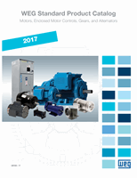
Single-phase Starter
WIRING DIAGRAM
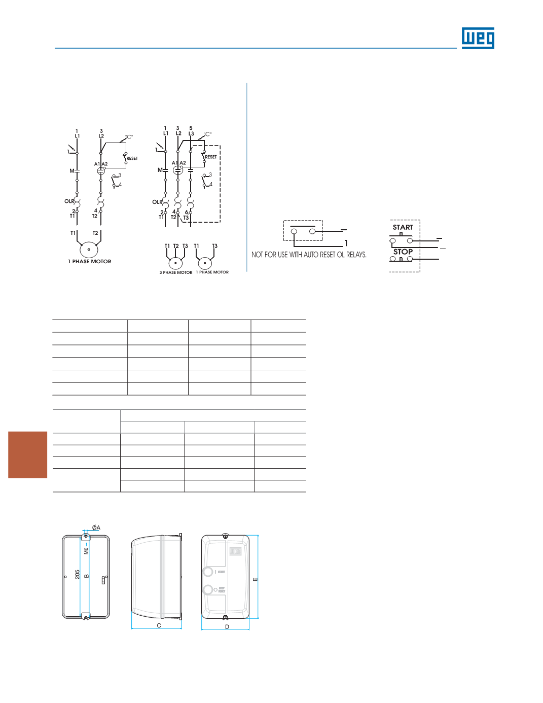
DIMENSIONS
SIZE 04 mm(in)
SIZE 06 mm (in)
SIZE 08 mm (in)
SIZE 10 mm (in)
øA = 4.5 (0.2)
øA = 6.5 (0.3)
øA = 6.0 (0.2)
øA = 7.0 (0.3)
B = 180 (7.1)
B = 205 (8.1)
B = 275 (10.8)
B = 355 (14.0)
C = 111 (4.4)
C = 126 (5.0)
C = 143 (5.6)
C = 167 (6.6)
D = 105 (4.1)
D = 120 (4.7)
D = 180 (7.1)
D = 250 (9.9)
E = 185 (7.3)
E = 210 (8.3)
E = 280 (11.0)
E = 360 (14.2)
Provision for
cable gland fitting
Standard
Top
Bottom
Back
Size 04
2 x 1/2’’
2 x 1/2’’
ø18mm (0.7in)
Size 06
2 x 1/2’’ and 3/4’’
2 x 1/2’’ and 3/4’’
ø22mm (0.9in)
Size 08
2 x 3/4’’ and 1’’
2 x 3/4’’ and 1’’
-
Size 10
2 x 3/4’’ and 1’’
2 x 3/4’’ and 1’’
-
1 x 1’’ and 1 1/4’’
1 x 1’’ and 1 1/4’’
-
Three-phase Starter
Separate Control
Pilot Devices
95
96
“D”
For wall mounting on starters size 08 and 10, four screws with the following
characteristics should be used:
• Pan, dome or rounded shaped head;
• Starter size 08:
* Screws size 1/4 (or M6 – ISO Standard);
* Dimensions: diameter thread shall be maximum 1/4 in
and diameter head shall be maximum 15/64 in.
• Starter size 10:
* Screws size 12 (or M5 – ISO Standard);
* Dimensions: diameter thread shall be maximum 0.236 in and diameter
head shall be maximum 0.394 in.
A1
3/1
4
A1
2 Wire Control
3 Wire Control
FOR SEPARATE CONTROL, REMOVE WIRES "C" AND "D" IF SUPPLIED AND
CONNECT SEPARATE CONTROL LINES TO TERMINAL Nº 96 ON THE OVERLOAD
RELAY AND TO TERMINAL Nº _3 ON THE AUX. CONTACT BLOCK (FOR 3 WIRE
CONTROL) OR TO THE CONTACTOR COIL Nº A1 (FOR 2 WIRE CONTROL).